- SMT Splice Tape
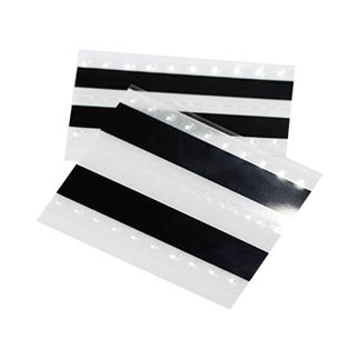
It is suitable for splicing a variety of SMT machine carrier belts
Products variations colors and images without any additional plugins. - Splicing Tape Tool
- SMT Splice Cart
- Cleaning Wipes
SMT Splicing Tape: How to Use It the Right Way (Step-by-Step Guide)
 Meta Description: Learn how to use SMT splicing tape correctly with this step-by-step guide. Covers splice tools, alignment techniques, common mistakes, and tips to avoid feeder jams and downtime. Written for SMT line operators and process engineers.Target Keyword: SMT splicing tape how to use
Secondary Keywords: how to splice SMT tape, SMT splice tape application, SMT splicing tool guide, SMT feeder splicing, SMT tape splicing best practices
URL Slug: /smt-splicing-tape-how-to-use-step-by-step-guide
If you run an SMT line, you already know the pain: a feeder runs empty mid-production, the machine stops, and you lose minutes — sometimes more — rethreading a new reel. That’s where SMT splicing tape comes in.
But here’s the thing: the tape itself doesn’t guarantee a clean splice. How you apply it does. A rushed job means feeder jams, mis-picks, or a splice that snaps halfway through a reel. A good splice, on the other hand, runs through the feeder like it’s not even there.
This guide walks you through how to use SMT splicing tape properly — from prep to verification — so your splices hold up on high-speed lines (Panasonic, Fuji, Siemens, Yamaha — doesn’t matter).
What You’ll Need Before You Start
Don’t grab the first roll of tape you see. Gather these first:
| Tool / Material | Why It Matters |
| SMT splicing tape (single or double-sided, matched to your carrier tape width) | The core of the splice. Wrong width = misalignment. |
| Splice tool or splicing pliers | Applies even pressure. Your fingers alone won’t cut it on high-speed lines. |
| Splice cutter or sharp scissors | Clean cuts on the leader/tail — ragged edges cause feed issues. |
| Copper clip / shim (if your feeder requires inductive sensing) | Machines like Panasonic and Fuji need the metal clip to detect the splice. |
| Clean work surface + lint-free wipe | Dust and oil on the tape = weak bond. |
| Anti-static wrist strap (for ESD-sensitive lines) | Static discharge near the splice zone can damage components. |
How to Use SMT Splicing Tape: Step-by-Step
Step 1: Match the Tape to Your Feeder and Carrier
Not all SMT splicing tape is the same. Before you even peel the backing, check three things:
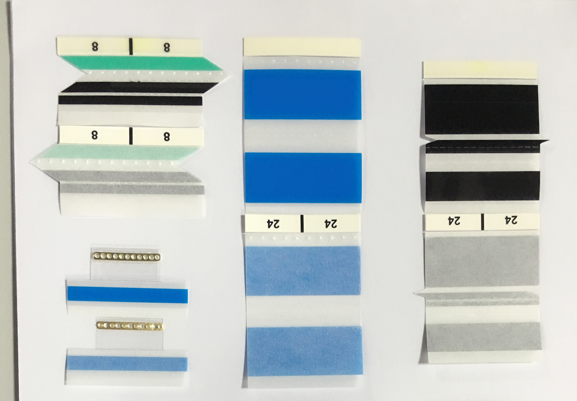
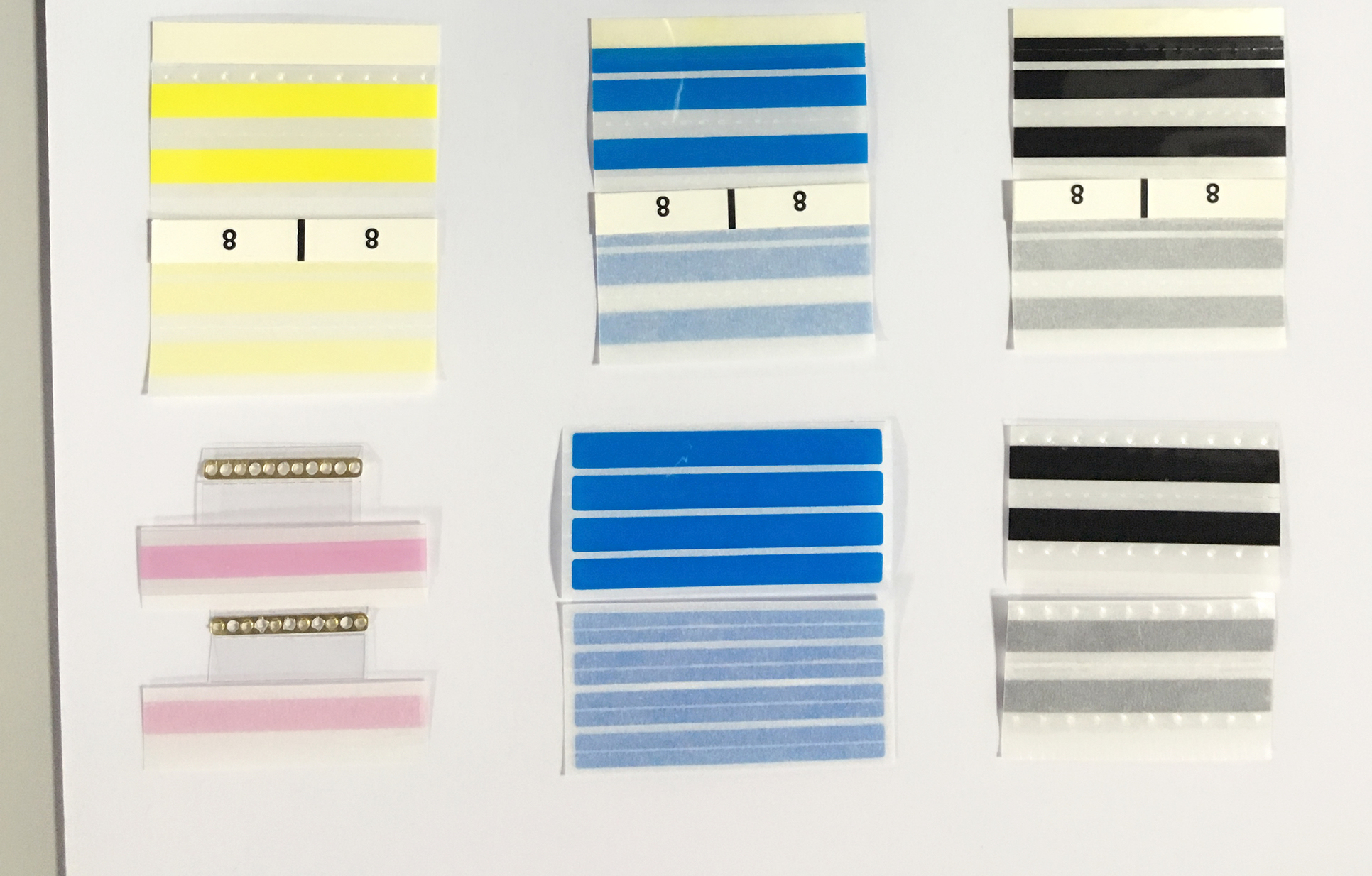
- • Width — Your splicing tape should match the carrier tape width exactly (8mm, 12mm, 16mm, 24mm, 32mm, 44mm, 56mm, 72mm — common sizes). Too wide and it catches on feeder guides. Too narrow and it won’t hold.
- • Type — Single-sided for standard splicing; double-sided for high-tension reels or heavy components; ESD-grade if you’re handling static-sensitive ICs.
- • Adhesive compatibility — Make sure the adhesive bonds to your carrier tape material (paper tape and embossed plastic tape behave differently).
Quick rule of thumb: If you’re running Panasonic, Fuji, or Siemens feeders above 0.1 sec/chip, use a double-sided splice with copper clip. For lower-speed lines or lighter reels, single-sided works fine.
Step 2: Prep the Reels
Don’t splice dirty or damaged tape. It won’t hold.
- 1. Cut the tail clean — On the depleted reel, trim the tail end so it’s straight. No frayed edges, no bent sprocket holes.
- 2. Cut the leader clean — On the new reel, cut the leader straight across. Remove any damaged or creased sections.
- 3. Wipe both ends — A quick pass with a dry, lint-free cloth removes dust and oil that kills adhesion.
Skip this step, and even the best splicing tape peels off after a few indexing cycles.
Step 3: Align the Sprocket Holes (This Is Where Most Splices Fail)
A misaligned splice is the #1 cause of feeder alarms and mis-picks. Here’s how to get it right:
- 1. Lay the two tape ends on a flat surface, component side facing the same direction.
- 2. Overlap them by one or two pitch distances — that’s the center-to-center distance between two adjacent component pockets. For a 4mm pitch tape, overlap by 4-8mm.
- 3. Line up the sprocket holes on the top and bottom tapes. Hold them up to a light source or use a splice tool’s alignment guide. If even one hole is off by half a millimeter, the feeder indexing will catch it.
- 4. Use the alignment mark — most quality splicing tapes have a reference line or alignment indicator printed on the backing. Line it up with the sprocket holes.
Pro tip: If you’re splicing on a Panasonic or Fuji line, invest in a splicing jig with alignment pins. It removes the guesswork and cuts splice time by half.
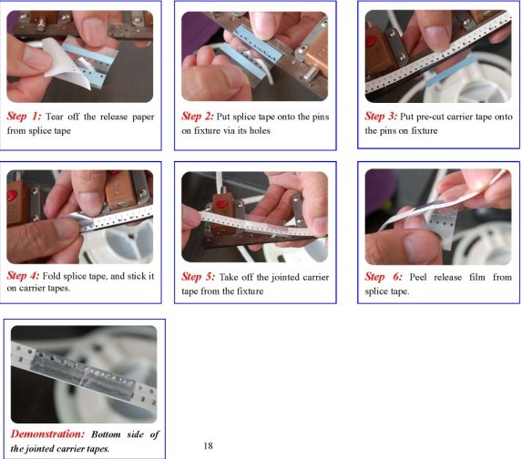
Step 4: Apply the Splicing Tape
Now the actual application:
- 1. Peel the backing off your splicing tape. Don’t touch the adhesive side — oils from your fingers weaken the bond.
- 2. Center the tape over the joint. The splice tape should fully cover both the tail and leader, with equal overlap on each side.
- 3. Press down firmly from the center outward. Use a splice tool or pliers — not your thumb. Even pressure across the entire joint is critical. Air bubbles or uneven pressure create weak spots that lift during indexing.
- 4. If using a copper clip / shim: Position it over the splice zone so the feeder’s inductive sensor can detect it. Most clips have an arrow — point it in the feed direction.
For double-sided splicing tape:
- • Apply the first side to the joint as above.
- • Flip the tape over, apply the second piece to the opposite side.
- • This gives you bond security on both faces — important for heavy reels or lines running above 50,000 CPH.
Step 5: Verify Before You Run
Never trust a splice without checking it. A 30-second verification saves 10 minutes of downtime.
- 1. Visual check — Look for adhesive overspill beyond the tape edges. Trim any excess with a cutter. Check that sprocket holes are fully clear on both sides.
- 2. Pull test — Give the splice a gentle tug. It shouldn’t separate or lift at the edges.
- 3. Feeder dry-run — Manually rotate the feeder mechanism through the splice zone. Watch for hesitation, binding, or skipping. If it snags at all, redo it.
- 4. Low-speed test — If your machine allows, run the first few indexes at reduced speed. Once the splice clears the feeder gate, ramp up to full speed.
Common Splicing Mistakes (and How to Fix Them)
| Problem | What’s Going Wrong | Fix |
| Splice breaks mid-run | Adhesive didn’t bond. Possible causes: dirty tape surface, expired tape, wrong tape type for material. | Clean both surfaces, check tape shelf life (<1 year), match adhesive to carrier material. |
| Feeder jams at the splice | Splice too thick or edges catching on feeder guides. | Use thinner splicing tape (check caliper spec), trim overspill, verify width match. |
| Mis-picks near splice zone | Sprocket holes misaligned — the feeder indexes unevenly. | Re-align. Use a jig with pins. Overlap by exactly 1-2 pitch distances. |
| Machine doesn’t detect splice | Missing copper clip, or clip placed backward. | Add clip, point arrow in feed direction, verify clip type matches machine spec. |
| Adhesive residue on feeder | Low-quality tape or tape used beyond temperature spec. | Switch to a production-grade splicing tape rated for your line temperature. Clean feeder guides with isopropyl alcohol. |
| Tape lifts at edges after a few cycles | Uneven pressure during application. | Use splice pliers, not fingers. Apply pressure center → outward. |
Single-Sided vs. Double-Sided: Which One to Use
The choice comes down to what your line demands:
| Single-Sided Splicing Tape | Double-Sided Splicing Tape | |
| Best for | Standard lines, lighter reels, paper carrier tape | High-speed lines, heavy reels, embossed plastic tape |
| Application speed | Faster — one piece per splice | Slower — two pieces, but more secure |
| Joint strength | Adequate for moderate tension | Holds under high tension and rapid indexing |
| Typical CPH range | Up to ~40,000 CPH | 50,000+ CPH |
| Copper clip compatible | Yes (on adhesive side) | Yes (sandwiched between layers) |
When in doubt, run a few test splices on an offline feeder and see which holds better under your line conditions.
Storage and Shelf Life
Splicing tape doesn’t last forever. Poor storage ruins adhesive performance before you even open the pack.
- • Temperature: Store at 20°C–30°C (68°F–86°F). Don’t leave rolls near reflow ovens or in direct sunlight.
- • Humidity: 45%–65% RH. High humidity degrades acrylic adhesives.
- • Shelf life: 1 year from manufacture date. Mark the date on the box when you receive it.
- • Storage position: Keep rolls flat or upright — don’t stack heavy items on top.
- • Opened rolls: Reseal in anti-static bags if not used within the shift.
FAQ: SMT Splicing Tape How to Use
Q: Can I use regular adhesive tape instead of SMT splicing tape?
No. Regular tape lacks the controlled thickness, anti-static properties, and adhesion stability needed for high-speed feeders. It’ll leave residue, jam your feeder, and cost you more in downtime than you save.
Q: How do I know which width of splicing tape to buy?
Match it to your carrier tape width. Common sizes: 8mm, 12mm, 16mm, 24mm, 32mm, 44mm, 56mm, 72mm. If you run multiple widths on the same line, stock an assortment.
Q: Do I need a splice tool, or can I just use scissors and my fingers?
For a low-speed line running occasionally, scissors + careful hands might work. For anything running regularly above 20,000 CPH, get a splice tool. It pays for itself in fewer jams and re-splices.
Q: How much overlap should I leave when splicing?
One to two pitch distances (typically 2-8mm depending on your tape pitch). More overlap = stronger joint but thicker splice zone. Find the balance.
Q: Why does my splice keep failing on the Panasonic feeder?
Panasonic feeders have tight gate tolerances. Check: (1) splice tape width matches exactly, (2) sprocket holes are perfectly aligned, (3) you’re using a copper clip for induction detection, (4) adhesive hasn’t expired.
Bottom Line
Using SMT splicing tape correctly isn’t complicated — but it is precise. Clean surfaces, matched widths, aligned sprocket holes, even pressure, and a quick verification before you run. That’s the difference between a splice that holds and one that sends you scrambling for the stop button.
If you’re looking for production-grade SMT splicing tape that works across Panasonic, Fuji, Siemens, and Yamaha feeders, KHB’s SMS16 series covers 8mm–88mm carrier tape widths with single-sided, double-sided, and ESD-safe options. Comes with copper clip pre-integrated — one less thing to fumble with during changeover.
Request a free sample →
SEO Notes for Publishing
Title Tag: SMT Splicing Tape: How to Use It the Right Way (Step-by-Step Guide)
H1: SMT Splicing Tape: How to Use It the Right Way (Step-by-Step Guide)
Meta Description: Learn how to use SMT splicing tape correctly. Step-by-step guide covering splice tools, alignment, common mistakes, and tips for Panasonic/Fuji/Siemens feeders.
URL: /smt-splicing-tape-how-to-use-step-by-step-guide
Featured Snippet Target: FAQ section (Q&A format)
Internal Links To:
- • KHB SMS16 product page
- • KHB splice tools page
- • KHB ESD splicing tape page
- • Related article: “The Ultimate Guide to SMT Splicing Tape” (existing)
Image Suggestions:
- 1. Step-by-step splicing process infographic
- 2. Sprocket hole alignment close-up
- 3. Splice tool application photo
- 4. Common mistakes visual comparison
- 5. KHB SMS16 product image with dimension callouts
Alt Text Examples:
- • “Aligning sprocket holes during SMT splicing tape application”
- • “Using splice pliers to apply SMT splicing tape on carrier tape”
- • “KHB SMS16 SMT splicing tape with copper clip for Panasonic feeder”
Schema Markup: HowTo schema or Article schema recommended